Our voltage controlled magnetic anisotropy (VCMA) model is made based on our STT model. This model initially includes experiment-based device parameters for VCMA effect. Furthermore, The VCMA model allows ones to adjust the MTJ dimensions, device parameters(i.e. VCMA coefficient, thermal stability factor, etc), and experimental parameters such as voltage pulse and external magnetic field. It also includes the effect of initial angle and thermal fluctuation for a more accurate physics-based MTJ switching.
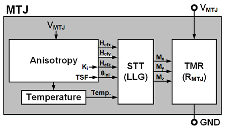
Block diagram of VCMA model
J. Song, I. Ahmed, Z. Zhao, S. Sapatnekar, J.P. Wang, C.H. Kim, ''Evaluation of Operating Margin and Switching Probability of Voltage- Controlled Magnetic Anisotropy Magnetic Tunnel Junctions", IEEE Journal of Exploratory Solid-State Computational Devices and Circuits (JxCDC), Apr. 2018 [LINK TO PAPER]
Switching mechanism |
Device |
Parameter (Default) | Download |
|||||
|---|---|---|---|---|---|---|---|---|
| Dimension | Material | Ms0 | P0 | Alpha | RA | |||
| Voltage controlled magnetic anisotropy (VCMA) |
Interface perpendicular MTJ | 70nm x 70nm x 1.49nm | CoFeB | 950 | 0.54 | 0.025 | 130 | VCMA_model.zip |
By using our MTJ compact model, you agree to acknowledge the
"UMN MTJ SPICE model, online: http://mtj.umn.edu" in your publications or presentations.
Step1.  Download MTJ spice model.
Step2.  Extract .zip file. STT model contains three separate zip files for in-plane, crystalline perpendicular and interface perpendicular MTJ.
Step3.  Open MTJ_write.sp file (MTJ write example)
Step4.  Set MTJ dimensions and material parameters: Ms0, P0, alpha, RA and initial temparature.
		For VCMA model, set VCMA parameter.
		Additionally, you can add thermal fluctuation (see Step7) in SHE and VCMA model.
                (Ms0: saturation magnetization, P0: polarization, both at zero Kelvin temperature.)
Step5.  Select anisotropy type using parameter 'MA':
	          ex) In-plane magnetic anisotropy: MA='0'
                         Perpendicular magnetic anisotropy: MA='1'
Step6.  Select the initial state of free layer using parameter 'ini', and apply voltage with correct polarity.
	       Magnetization of the fixed layer will be set automatically according to the 'ini' value.
	           ex) Antiparallel to parallel switching : ini='1' with positive voltage
	                  Parallel to antiparallel switching: ini='0' with negative voltage
Step7. Setting thermal fluctuation: A default thermal fluctuation SPICE file is already given.
	   Use the MATLAB code, "NoiseGen_MATLAB.m" to create thermal fluctuation SPICE file for a different parameter.
	   By setting the parameter x_thermal = 0, in the LLG_solver.inc file, the thermal fluctuation can be omitted.
Step8.  Run SPICE simulation
This work was supported in part by C-SPIN, one of six centers of STARnet, a Semiconductor Research Corporation program, sponsored by MARCO and DARPA.